|
The program that moves servo-motors (“fingers”) consists of one minor part and two major ones (Fig. 41b), separated by comments in grey:
-
Setting the rotation speed (rotationStep variable, pink) – while transferring the program to a real UNO, one can shift this statement into the setup() procedure.
-
Giving instructions for each servo-motor to rotate to a certain position – 5 outputs (blue), where one should be careful to specify the correct output pin (on the UNO board) and position (different variables, pink). As these variables are set by default to 0 during the setup(), nothing happens after a power-on, until any button is pressed.
-
Checking the button pairs and recalculating the position of servo-motors. This part is repeated (only one visible in Fig. 41b) 5 times for each set of 2 buttons and a servo-motor.
-
The state (voltage) of button ”Up” is read from an analog input. The possible read-out range is from 0 to 1023 units, corresponding to 0 and 5 Volts respectively. One should be careful to specify the correct input pin on the UNO board.
-
If the read value is greater than 256 (1.25V), then the position of a particular servo-motor should be recalculated, increasing it by a value of rotationStep;
-
The calculated position should not exceed 180°. If it happened, it is set to this limiting value.
-
If the button “Up” was not pressed, the else branch is executed.
-
The state of button ”Down” is read from a digital input (0 = No, or 1 = Yes). One should be careful to specify the correct input pin on the UNO board.
-
If the read value is greater or equal 1, then the position of a particular servo-motor should be recalculated, decreasing it by a value of rotationStep. An additional arithmetic (math, green category) operation was necessary to obtain a negative value of rotationStep).
-
The calculated position should not drop below 0°. If it happened, it is set to this limiting value.
|
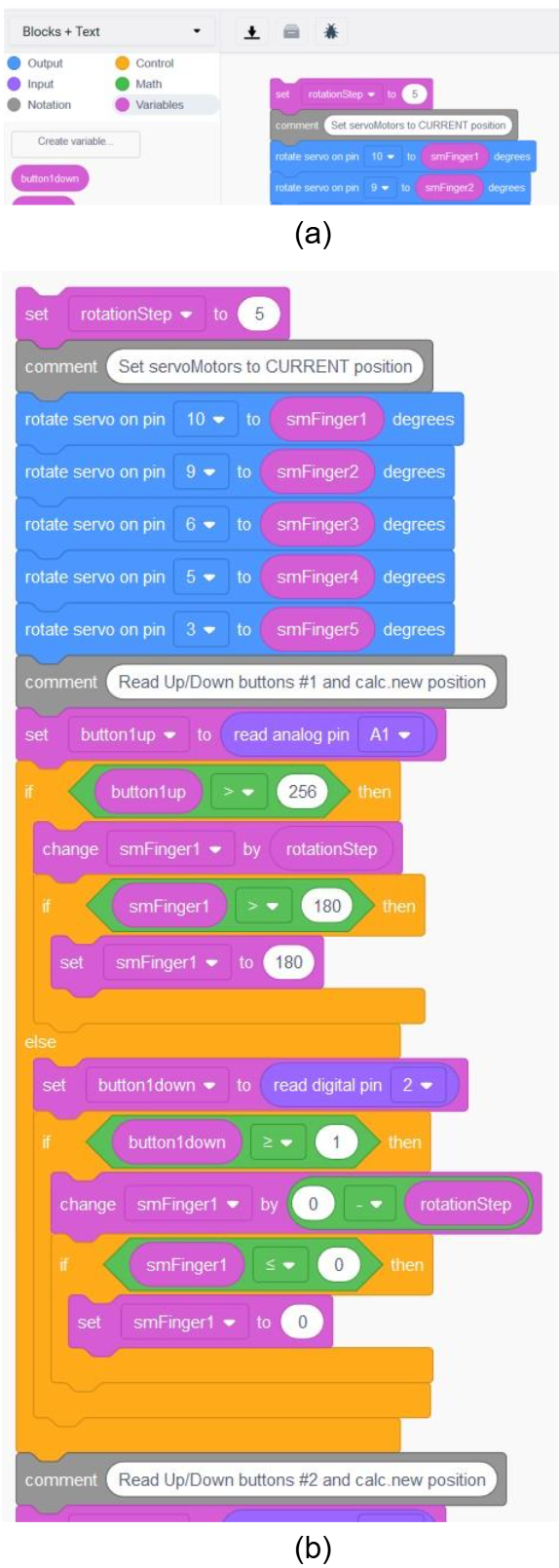
Figure 41. Part of graphical program for actuating servo-motors
|