2. Program Interface and Main Elements
Main Modeling Tools
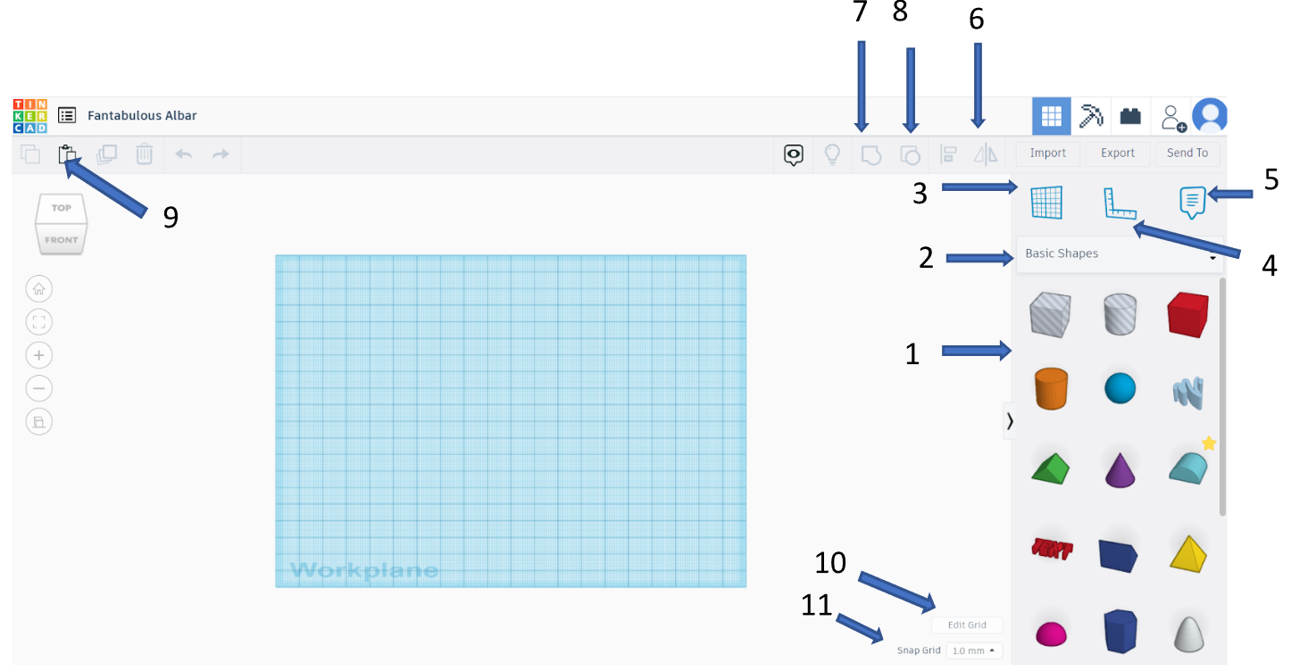
Figure 7. Main Modeling Tools
1 – Basic Shapes Library. This is the primary collection of 3D shapes used for modeling.
2 – Shape Library Selection ("Basic Shapes"). Clicking this option opens a menu with additional libraries containing more shape options.

Figure 8. Standard Shape Library Options
3 – Workplane Tool. Allows you to change the active workplane, meaning the surface on which new parts are designed.
4 – Ruler Tool. Can be placed on the workplane or directly on a specific object to measure and align elements accurately.
5 – Notes & Comments Tool. Used for communication between users or for adding personal notes to the project.
6 – Mirror (Symmetry) Tool. When designing symmetrical objects, instead of drawing both sides separately, you can create one side and then mirror it.
7 – Grouping Tool. When designing an object made of multiple separate parts, you can group them into a single solid model. Without grouping, the model remains just a collection of separate parts
8 – Ungrouping Tool. The opposite of grouping. This tool is useful when you need to modify an object by separating it into smaller parts.
9 – Copy & Paste Tool. Instead of clicking this tool, you can also use the keyboard shortcuts CTRL+C (copy) and CTRL+V (paste).
10 – Grid Editing Tool. Adjusts the scene grid, allowing you to increase or decrease the density of grid divisions in both directions.
11 – Grid Snap (Step Size) Tool – Determines the precision of object movement. Smaller step size allows for more detailed adjustments when working with tiny objects. Larger step size is useful when working with bigger models, where extreme precision is unnecessary.