4. Modeling concept and basic manipulations
| Website: | Bios4You |
| Kurs: | (4) Robotics in Biotechnology |
| Buch: | 4. Modeling concept and basic manipulations |
| Gedruckt von: | Επισκέπτης (Guest user) |
| Datum: | Dienstag, 25. August 2026, 06:42 |
Modeling concept and basic manipulations
Before to start modeling, we need to understand the basic principles and differences between three-dimensional and two-dimensional modeling.
Two-dimensional modeling is working in a plane. In other words, we model on a sheet of paper where we can draw across and along the sheet. In the design language, this is horizontally or vertically, or in the x and y axis directions
Three-dimensional modeling differs from two-dimensional by one more axis, which usually indicates the height of the model. Thus, three-dimensional models are designed on the x, y, and z axes.
Creating a model, it is not enough to imagine what it should look like. Its specific dimensions are needed. When creating a three-dimensional model, measurements are required with respect to the x, y, and z axes. In other words, a description of the model with x, y, and z projections is required. The projection is a two-dimensional plane aligned perpendicular to the two axes, the direction of the third axis being perpendicular to us. Another important highlight is the marking of visible and invisible lines. The visible line is the kind of edge that we see from the observer's point of view, it is not covered by anyone. The invisible line (red in Figure 1) is the edge which, when viewed from the observer's point, is covered by a plane closer to the observer.
Projections are an agreement document between engineers with not only drawings but also dimensions on them. With such dimensional drawings, it is easy to create a three-dimensional model with any program that is convenient for us. For example, you need to model a box of certain dimensions with a cylindrical hole. In order to model, we first need projections with dimensions. Only then it can be modeled accurately.
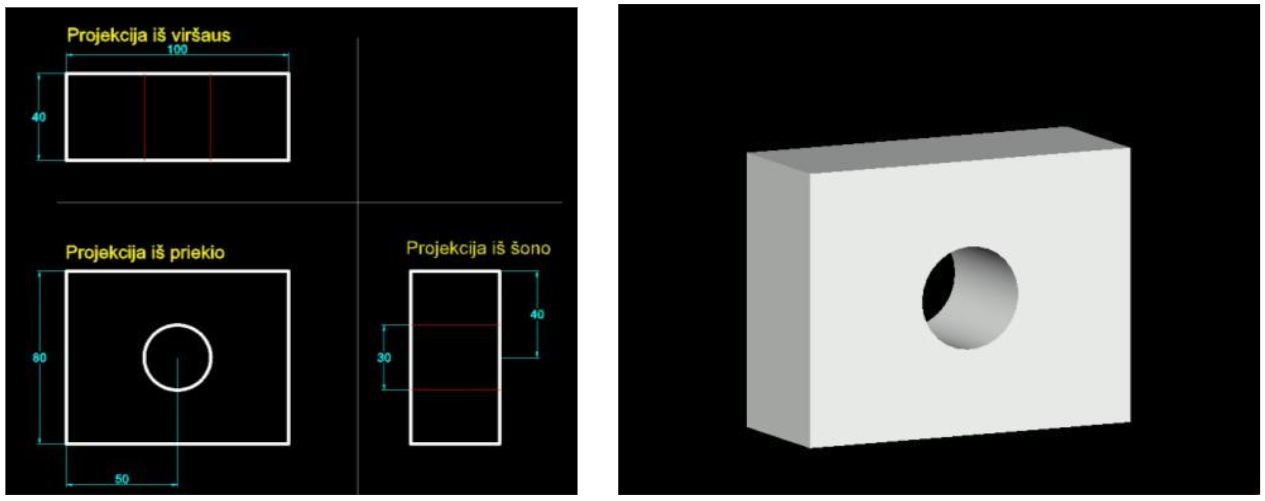
Figure 21. Detail projection with dimensions and its three-dimensional model
Simulation of TinkerCad program
To understand the simulation process, let’s try the open source virtual program TinkerCad.
- Click on the link →https://www.tinkercad.com/dashboard. Clicking "Creat new design" prepares the desktop.
- Drag the cube into the empty space from the toolbar on the right. On the left side of the window, the navigation tool (cube-shaped) must be set to “Front”.

Figure 22. Editing parameters of cube

Figure 23. Scene view after grouping
- To change the parameters of a cube, clicking on it opens a window with the parameters next to it (Figure 22).
- The program allows you to choose from different types of shapes. Possible settings are a convex model or a recess (or hole) in its shape.
- Select the sphere tool, load it in the top plane of the box, and set the hole parameter. This will give us a spherical recess in the cube.
- Place two cylinders on the different edges of the box. Set the property to "solid" for one and "hole" for the other. The shapes assigned to the "hole" feature look like glass. But this is only an imaginary part of that figure. In order to "cut" holes in the box, all parts of the scene need to be grouped.
- Select all objects in the scene and select the "group" function (Figure 23).
- All you have to do is export the prepared model to * .stl file (Figure 24). You can choose to print the entire model or specify specific parts.
- There is also the option to save the model, or print directly. TinkerCad has the ability not only to print the model, but also to cut it with a laser machine.

Figure 24. Exporting a file
Creating an accurate model
If you notice, the TinkerCad workspace has a horizontal platform on which we design the model. It is possible to change the grid of this base, its step. The step of movement of the part will depend on it (Figure 25).
The grid does not have an absolute coordinate system. That is, where you placed the shape, the program calculates the start of the coordinates. Dragging the object, the deviation is calculated relative to the previous location.

Figure 25. Change the grid step
According to the modeling rules, the model is projected into an XY plane that coincides with the ground. To project in a different direction, you must first change the working plane.
Let’s try to design the model of Figure 26 (1).
- Let’s drag the cube into the working field and set its dimensions 40x100x80
- Also drag cylinder to the scene. If you notice, the background of the cylinder coincides with the working plane. We can solve this problem in two ways:
-
- Change the working environment to the side of the box
- Rotate the cylinder 90 degrees to the x axis
Changing the working plane. Select the "workplane" icon (Fig. 26 (1)) and click on the box wall (Fig. 26 (2)). Now that the cylinder is pulled, its base will coincide with the new working plane, which means with the side plane of the box.
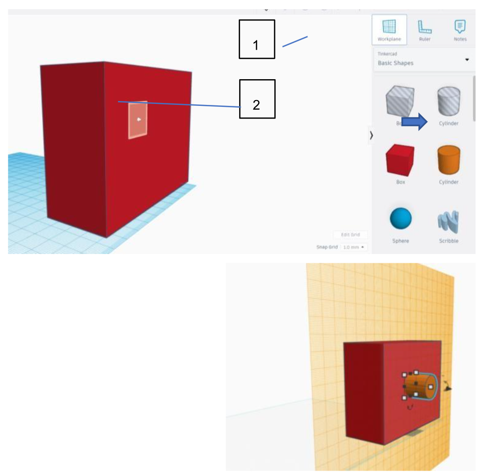
Figure 26. Changing the working plane
Cylinder rotation. Drag cylinder and select it. Click on the arrows showing the rotation with respect to the x-axis and set the rotation angle to 90 degrees.
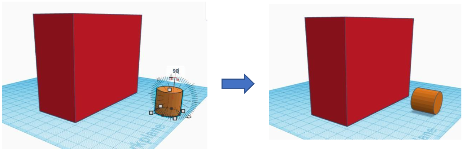
Figure 27. Rotation of the cylinder with respect to the x axis
3. Location of cylinder hole. For moving cylinder to special location, we must change working plane to the side of the box. So it is better to change it before including cylinder shape.
-
- Align both shape by one edge.
- Move cylinder 35 mm to the right and 25mm to the top
- Change working plane to the ground and set navigation bar to TOP
- Move cylinder vertically and fit to the box (Figure 28)
4. Now as cylinder is in correct place, we can change type of shape to “hole”
5. Select both shapes, set “group”
6. Export file to *.stl
Figure 29 shows how final model looks in TinkerCad program (left) and as *.STL file (right)
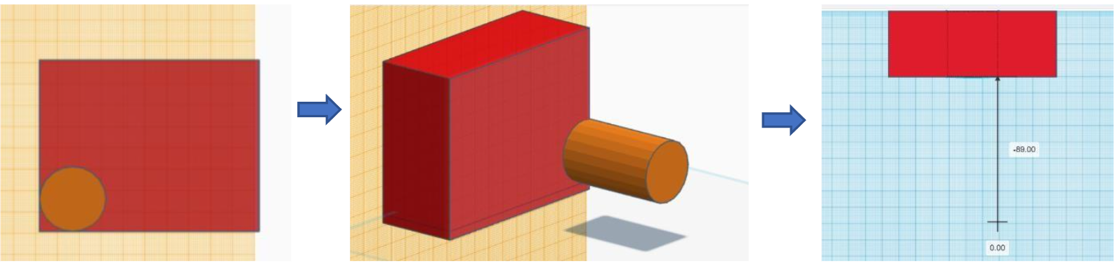
Figure 28. Moving cyliner
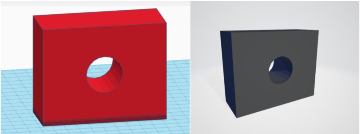
Figure 29. Final model in TinkerCad environment and *.stl file
TinkerCad is convenient to try modeling tool for beginners. For complex projects it is better to choose Blender program.
Short review, how this simple model could be created using blender. Default view of starting program is in image 30. Default shape is cube, units – meters, length 2m.
Steps to begin:
- Change units to millimeters
- Change length of edges to x, y and z axis 40x100x80
- Select shape and press CTRL+A and select Scale. With this operation we set new shape of box as default.
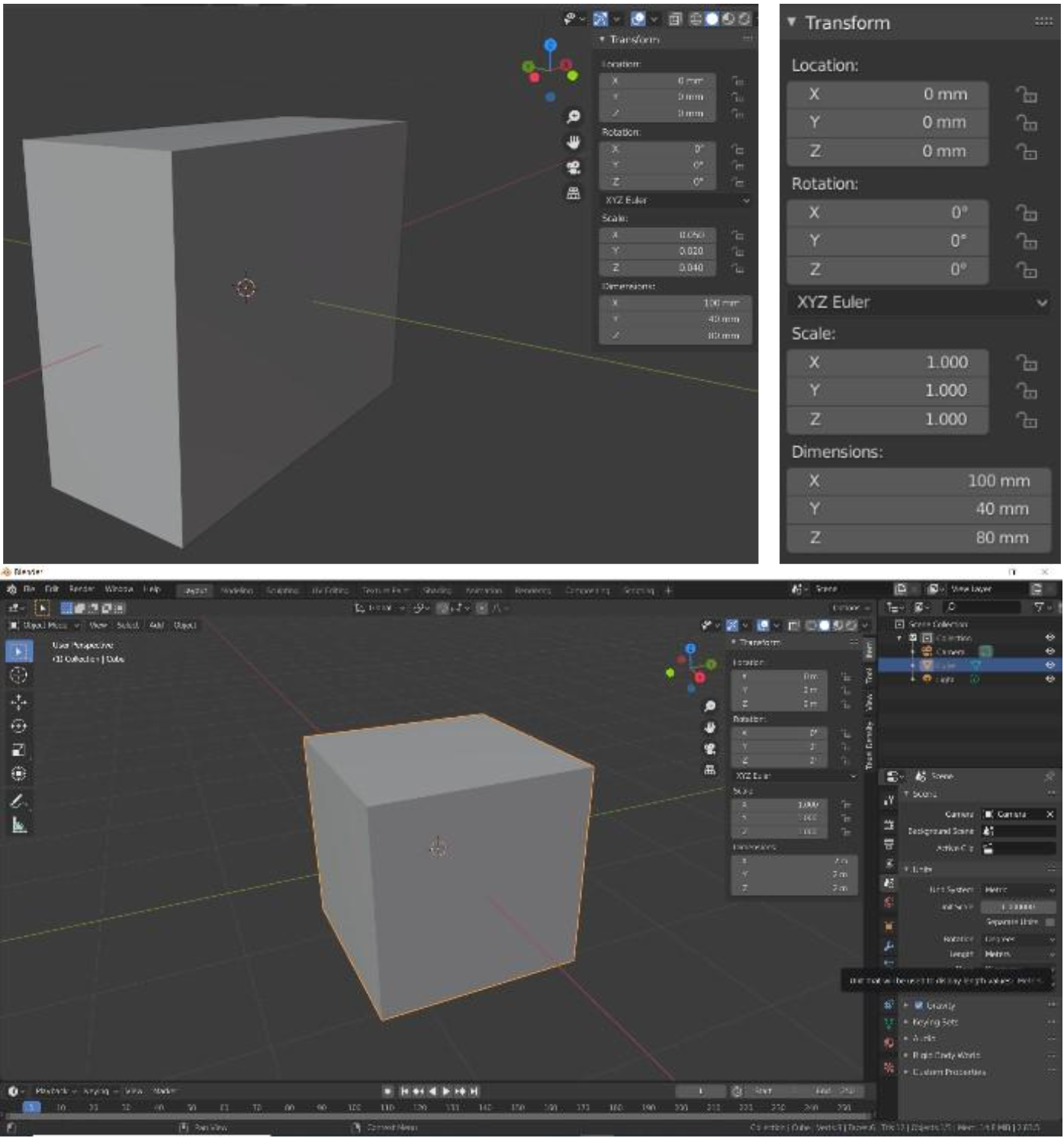
Figure 30. Box transformation
-
Press Tab to switch to Edit Mode
-
Press SHIFT+A and select Cylinder shape.
-
This shape by default is oriented by Z axis (Figure 31). So we need to change options of it:
-
- Radius of background is 15mm
- Rotate by Y axis 90 degrees

-
Now we have two duplicated planes – box and cylinder background. Delete theses planes (two backgrounds of box and two of cylinder).
-
To make a plane between edges of box and cylinder auxiliary edges are needed. It is simple to calculate distance between point of circles diameter and box edge horizontally. It is 35mm. Select circles diameters point, press E (extrude), lock Y axis and set 35 (Figure 32). At the top left corner you can check what options are set.

Figure 32. Auxiliary edge for planes
-
The same step for opposite side of circle. And for opposite background.
-
Now as we have auxiliary edges, dividing background plane to two part, we can select separately parts as it shown in Figure 33a. Then press “F” (Face). The Face is created between selected points (Figure 33b)
-
Make the same step to second part of background. Also the same steps for opposite background.
-
Press TAB to switch to Object mode.
-
The last step is to export to *.stl file: File>Export>(*.stl)
-
The view of final shape in Blender program and exported to *.stl file is shown in Figure
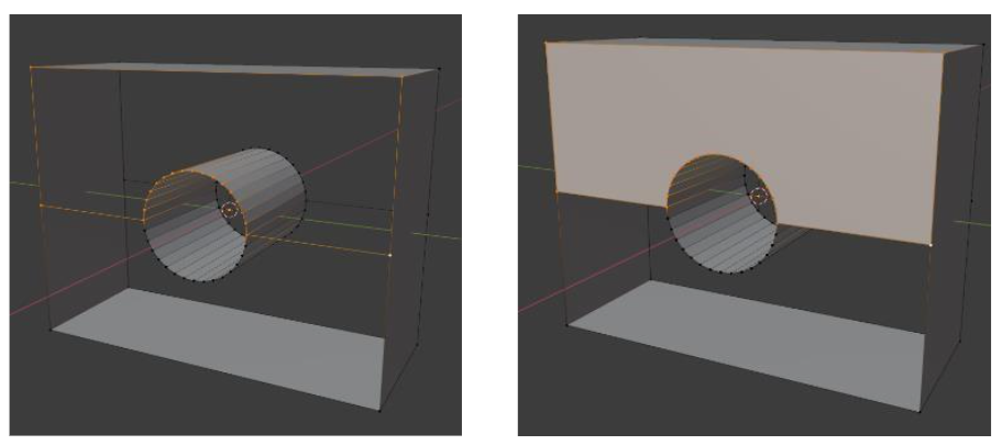
Figure 33. Select points(a) and create Face between them (b) 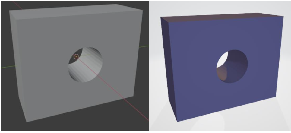
Figure 34. Final object in Blender enviroment and created *.stl file
It seems Blender is easer tool to create such model. But you have to know a lot of things to use it, such as different modes for editing, for plane direction and ect.
Notes: After completing basic modeling tasks, students can project their 3D designs onto their workspace using AR tools. This allows them to better understand the proportions and spatial relationships of their designs, ensuring accurate alignment of mechanical parts.
Enhanced with AR
Before finalizing your 3D model, use Merge Cube to hold and manipulate virtual components of the bionic finger. This hands-on interaction helps students better understand the spatial relationships between mechanical parts, ensuring precise alignment and functionality in the final prototype.