5. Making the fingers move
| Site: | Bios4You |
| Kurs: | (4) Robotics in Biotechnology |
| Kitap: | 5. Making the fingers move |
| Tarafından basılmıştır: | Svečio paskyra |
| Tarih: | Salı, 25 Ağustos 2026, 5:56 AM |
Overview
As it was shown before, one of the easiest ways to deploy motions of the bionic hand could be by a servo motors that are pulling strings (“tendons”), connected to furthermost moving part of a finger (see Fig.35).

Figure 35. Moving a finger of the bionic hand
The motors could be controlled by a comparatively autonomous electronic device - a single board computer (SBC) of a size of a credit card. There are plenty of such devices on the market, but the suggested one is the Arduino UNO microcontroller (see Fig.36), because:
- It is open-source based, comparatively cheap and extremely popular among the enthusiasts in electronics and small automation;
- It is included as one of simulated virtual devices in a Tinker CAD – a web-based free platform for design learning. This is a particular advantage as 3D modelling, circuit and software design could be performed within the same environment. Furthermore, the virtual design, modelling and testing of the hardware and the software will help to avoid save equipment damage (therefore- some expenses), as the virtual hardware elements does not get out of order, if connected and used improperly. Some recommended preventive preparation steps before deploying the design in a real hardware will be mentioned below.
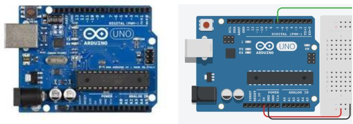
Figure 36. Arduino UNO microcontroller (real view- left, virtualised in TinkerCAD- right)
Arduino UNO microcontroller
The Arduino UNO microcontroller (here and thereafter referenced as “UNO”) has limited computational resources comparing to desktop PCs, laptops, tablets or even mobile phones, but it is completely suitable for our task – deploying a controlled motion:
- UNO could be connected to a Windows PC through an USB cable, to supply the power and to load a software program;
- The software is usually developed in a limited version of C programming language inside a special Arduino software development environment called SKETCH. It is worth to mention, that the software could also be designed and tested in the Tinker CAD, then exported as a file, read by SKETCH, compiled and loaded to an UNO device.
- The UNO with loaded program can operate without a PC and control connected devices, when powered independently (7-12 Volts DC power supply or 9V battery recommended).

Figure 37. Arduino UNO microcontrolled and SKETCH programe development environment. One can notice the only two procedures executed by UNO, that should be designed: setup() – initialisation of a SBC; and loop() – to be repeated until the power is supplied.

Figure 38. „Circuits“ section (left column) in Tinker CAD
Arduino UNO in Tinker CAD
The electronics and software design modelling happens entering the “Circuits” section (Fig. 38) in the Tinker CAD (the “3D design” section might have been used before for modelling parts of fingers). One can find a comprehensive library of Tinker CAD examples and designs for learning.
The graphical development environment of the Tinker Cad contains 2 parts: a virtual electronics on the left and electronic elements collections or programming editor on the right (as seen on Fig. 39). The latter could be used in two alternative modes:
- C program editor, like in SKETCH – one can export a C program file to be loaded to a real UNO;
- Graphical programming environment “CodeBlocks”, extremely similar to SCRATCH2. The CodeBlocks program is automatically converted to a C program (but it is not a case in opposite direction, one should be careful not to lose own work).
There will be 5 servo-motors used to move fingers of the bionic hand in the virtual experiment, schematically shown on Figure 39 and Figure 40. The motors will be controlled and driven by the UNO, and 10 buttons (5 fingers x 2 directions = 2 rows of buttons) will be used to initiate the motion.
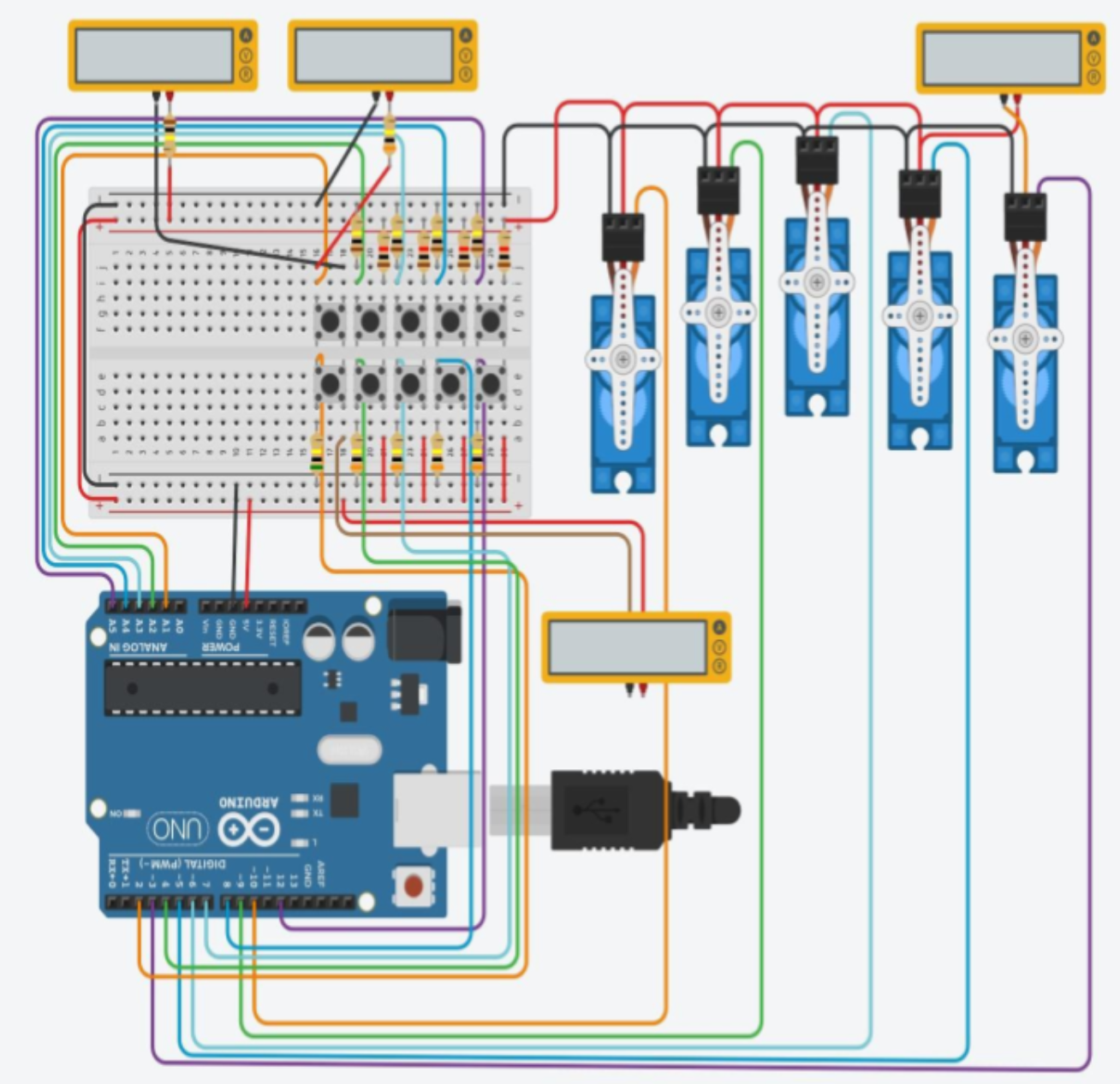
Figure 40. The virtual experiment - moving 5 servo-motors (fingers) by UNO. There are additional multimeters used to check the current through buttons and a servo-motor, in order to avoid possible overload
The servo-motor is a digital device, turning a spindle to a given position (usually from 0 to 180 degrees). The motors (control pins) should be connected to PWM (Pulse-Width Modulation – the way to specify a rotation position) marked digital outputs of the UNO. Totally, there are 6 such (PWM) digital outputs in an UNO.
One set of buttons (e.g. “Up”) will be connected to analog inputs of an UNO, another set (e.g. “Down”) of buttons - to digital inputs of an UNO. It should be mentioned, that connecting a button to an analog input and reading the value requires slightly more efforts than a to digital one.
2 Graphical programming environment, designed by MIT.EDU and widely used to teach programming at schools https://scratch.mit.edu/
Developing a program
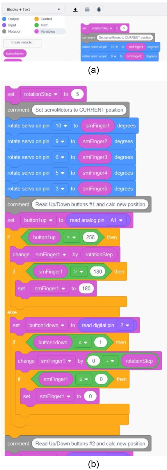
The Tinker CAD graphical programing environment (GPE) is limited to the development of the loop() function only, the setup() is deployed as default. That minor limitation could be overcome continuing further development only in C (no CodeBlocks), what might be acceptable for bigger practical applications. The GPE contains 6 kinds of “CodeBlocks” operations, coded in different colors (Fig. 41a): variables, control, output, input, math (includes calculation of meeting a condition, so called Boolean operations, used within control statements), notation (comments). The statements of different kinds are combined with each other according their shapes.
|
The program that moves servo-motors (“fingers”) consists of one minor part and two major ones (Fig. 41b), separated by comments in grey:
|
Figure 41. Part of graphical program for actuating servo-motors |
Proceeding further
There are some precautions one should take into account when trying to assemble a real working hardware model:
- The servo motors are of different power and might require different power supply schemes, as the UNO board may not supply enough power, especially when powered through USB connection.
- In real life it might be useful to employ a force sensor at the end of each finger and use it for stopping a motion. Such sensors could be read through analog inputs, therefore different setup for buttons (rearrangement and additional components) will be necessary.
To begin on your own…
There is a design one is suggested to start with (in the Tinker CAD) presented on Fig. 42:
- Simply take a virtual UNO and a virtual servo-motor.
- Connect power supply and ground from the UNO board to corresponding pins of a servo-motor, and PWM marked output of the UNO to the “Signal” pin of a servo-motor. Create a program rotating the servo motor to some position and back.

Figure 42. Suggested scheme for the first simulation
Suggested reading
AR-based motion simulations
Before uploading code to physical microcontrollers, students can use AR to simulate the finger movements virtually. This ensures that the programmed motions are precise and reduces the risk of mechanical errors or damage to components during real-world testing.