2. Program Interface and Main Elements
| Site: | Bios4You |
| Course: | (5) Let's Create a World with Tinkercad |
| Book: | 2. Program Interface and Main Elements |
| Printed by: | Guest user |
| Date: | Saturday, 24 October 2026, 2:58 PM |
Program Interface
After logging into your Tinkercad account, you will see the main interface.
Main Interface Sections:
-
– Account Information – Here, you can check and update your personal account settings.

Figure 4. Personal Account Information
-
– Teaching Tools – Standard guidelines are provided for teaching how to use Tinkercad. You can also create a custom teaching plan.
-
– Learning Tools – Lessons on how to design specific models.
-
– Blog – A space where users share their experiences and insights on 3D modeling with Tinkercad. You can also create your own blog
-
– Project Gallery – Most created designs can be downloaded as finished products. You can also download and modify existing models.
-
New Modeling Workspace Setup – This feature allows you to prepare a new modeling environment, which we will discuss in more detail in the next section.
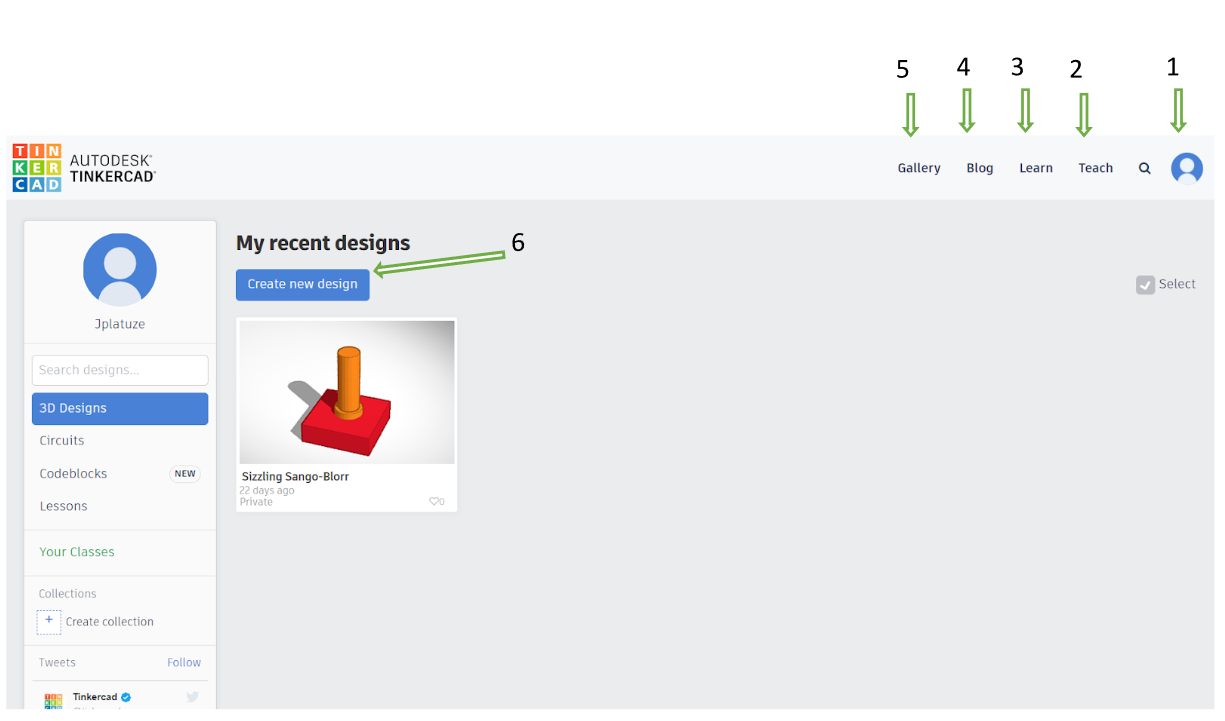
Figure 5. Workspace Environment
Key Interface Elements
When you select "Create New Design", a new window opens with the main modeling tools and interface elements.
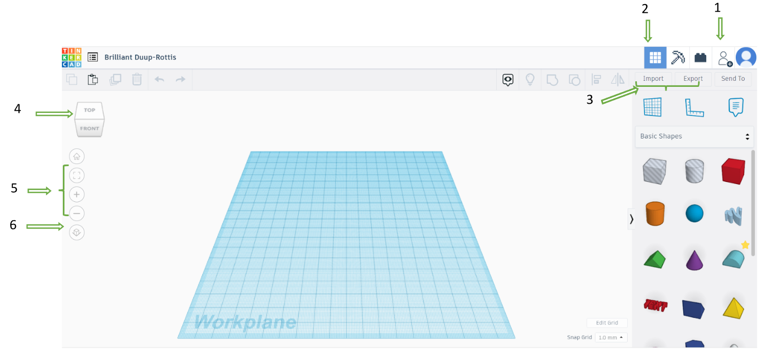
Figure 6. Main Parts of the Workspace
1 – Collaboration Tool. This feature allows multiple users to work on the same project. A unique link is generated, which can be shared with other users. Any changes made by one user are visible to others in real time.
2 – 3D Design Space. The main workspace where all modeling tools are available.
3 – Import and Export Tools. "Import" allows you to upload another project or a part of it into the scene. "Export" enables you to download your design in a specific format. For example, to prepare a project for 3D printing or CNC cutting, export it in .stl format.
4 – Navigation Tools. These tools allow you to move the entire scene and set different viewing angles (front, side, top, etc.). Note that this tool rotates the entire scene, not individual objects. You can also rotate the scene using the right mouse button.
5 – Zooming Tools. These tools allow you to zoom in and out on the scene view.
6 – View Mode Tool (Orthogonal or Perspective). Perspective Mode simulates real-life vision, where objects appear smaller as they move further away, and parallel edges converge at a vanishing point. Orthogonal Mode helps with precise modeling by displaying all parallel edges as truly parallel, ensuring accurate alignment and true-size representation of objects.
Main Modeling Tools
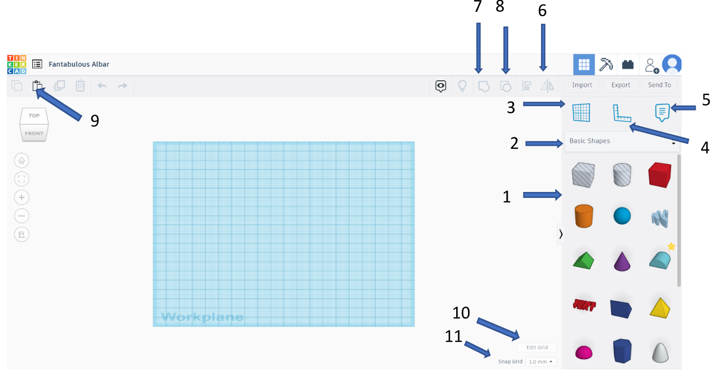
Figure 7. Main Modeling Tools
1 – Basic Shapes Library. This is the primary collection of 3D shapes used for modeling.
2 – Shape Library Selection ("Basic Shapes"). Clicking this option opens a menu with additional libraries containing more shape options.

Figure 8. Standard Shape Library Options
3 – Workplane Tool. Allows you to change the active workplane, meaning the surface on which new parts are designed.
4 – Ruler Tool. Can be placed on the workplane or directly on a specific object to measure and align elements accurately.
5 – Notes & Comments Tool. Used for communication between users or for adding personal notes to the project.
6 – Mirror (Symmetry) Tool. When designing symmetrical objects, instead of drawing both sides separately, you can create one side and then mirror it.
7 – Grouping Tool. When designing an object made of multiple separate parts, you can group them into a single solid model. Without grouping, the model remains just a collection of separate parts
8 – Ungrouping Tool. The opposite of grouping. This tool is useful when you need to modify an object by separating it into smaller parts.
9 – Copy & Paste Tool. Instead of clicking this tool, you can also use the keyboard shortcuts CTRL+C (copy) and CTRL+V (paste).
10 – Grid Editing Tool. Adjusts the scene grid, allowing you to increase or decrease the density of grid divisions in both directions.
11 – Grid Snap (Step Size) Tool – Determines the precision of object movement. Smaller step size allows for more detailed adjustments when working with tiny objects. Larger step size is useful when working with bigger models, where extreme precision is unnecessary.