
3. Task “Hollow Cylinder Modeling“
Before starting the task, take a moment to visualize the final outcome using the Tinkercad AR Viewer1 and using projects: https://www.tinkercad.com/search?q=cylinder&staffPicks=0 or by scanning the provided QR codes or exporting sample models into the AR viewer (CoSpaces EDU, XR viewer, AR Viewer – Augment, etc.) you and your students will be able to see the 3D models projected into your real-world environment through your mobile device. This will help you better understand the structure, proportions, and details of the object before you begin modeling. Exploring sample designs in augmented reality will give you a clearer idea of what to aim for, making the modeling process smoother and more intuitive.
QR example for Hollow Cylinder into Cospaces (https://edu.cospaces.io/WJF-DHM)

1.1. Objective: Create a hollow part where:
- The outer ring dimensions are 100x100 mm
- The inner ring dimensions are 90x90 mm
- The height of the part is 60 mm

Figure 9. Hollow Cylinder Modeling
1.2. Insert a Cylinder:
- Open the Basic Shapes Library and select a solid cylinder.
- Click and drag the cylinder onto the workplane.
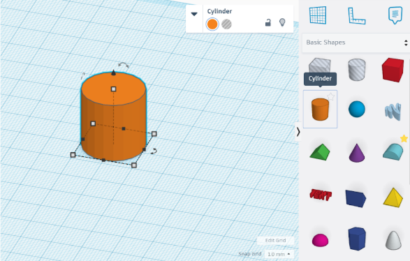
Figure 10. Inserted Standard Solid Cylinder
1.3. Adjust Cylinder Dimensions:
- Select the base of the cylinder.
- Click on the square handles that define its dimensions.
- Change the values to 100x100 mm.
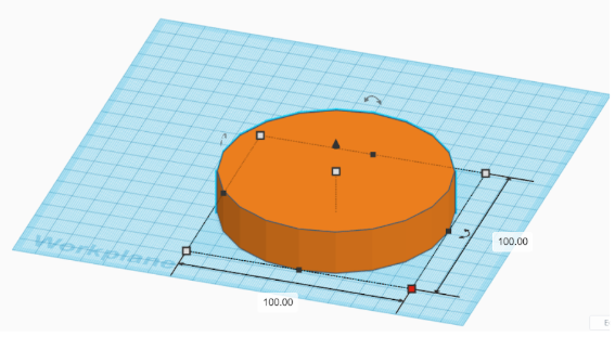
Figure 11. Adjusting Cylinder Dimensions
- To adjust the height, rotate the view to side perspective.
- Click on the top square handle and set the height to 60 mm
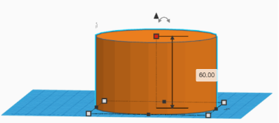
Figure 12. Adjusting Cylinder Height
1.4. Creating the Hollow Section. A hole can be modeled using the same cylinder by changing the part style from solid to empty space.
- Insert another cylinder from the Basic Shapes Library.
- Set its base dimensions to 90x90 mm.
- Set its height to 90 mm (larger than the outer cylinder to ensure a clean cut).
- Insert a ruler to assist with precise alignment and let's identify it with the square of the cylinder (when viewed from above):
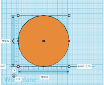
Figure 13. Inserting a Ruler
-
Move the smaller cylinder and align it to the corner of the ruler.
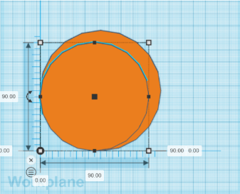
Figure 14. Aligning the Second Cylinder with the Ruler
-
To center the smaller cylinder inside the larger one, adjust its position by setting the offset values to 5 mm in both directions.
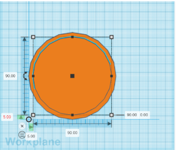
Figure 15. Centered Inner Cylinder
-
Convert the inner cylinder into a hole by selecting the "HOLE" option in the properties panel.
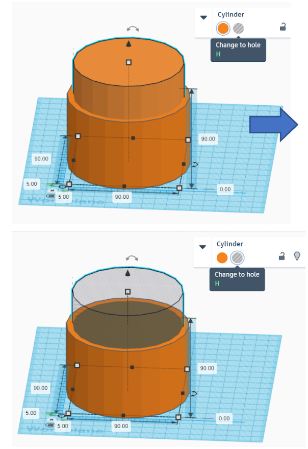
Figure 16. Changing Cylinder Material to "HOLE"
1.5 Grouping the Cylinders to Create the Hollow Shape:
- Select both cylinders (outer and inner).
- Click "Group" to combine them and remove the hollow section.
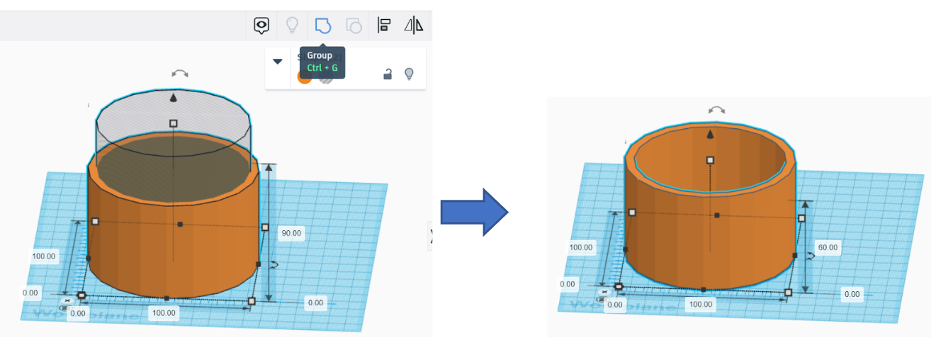
Figure 17. Grouping the Parts
1.6. Exporting for 3D Printing
- Click "Export" to prepare the file for 3D printing.
- In the pop-up window, select ".STL" as the file format.
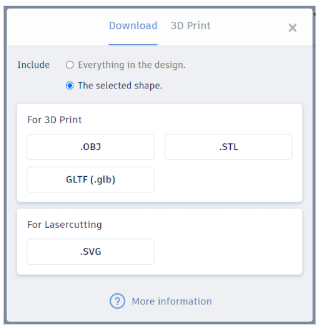
Figure 18. Selecting STL File Format for Export
The file is now ready for 3D printing!
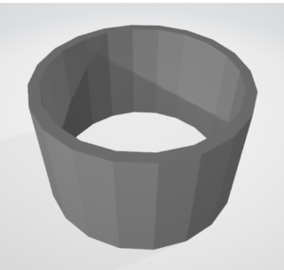
Figure 19. Detail preview
Enhance with AR. AR Visualization in the Real World: After creating their 3D models, students can export their designs not only in .STL format for 3D printing but also to an AR viewing platform, such as Tinkercad AR Viewer, Sketchfab, or WebAR solutions. This will allow them to project their created objects into their real-world environment using a smartphone or tablet. For example, a student could "place" their designed trophy on an actual table to see how it looks in a real-life setting.
1 Officially available for the Apple iPad as a free download from the App Store.